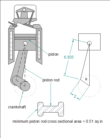
1. Problem Statement: Determine the acceleration equation for the engine piston rod in Figure 1 as a function of crankshaft angle and crankshaft RPM. Use the accelation equation to determine connecting rod stress at a function of RPM and crank angle. Ignore connecting rod mass.
Using calculus, derive the following equations as a function of q:
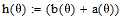
a) the piston displacement equation
b) the piston velocity equation
c) the piston acceleration equation
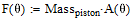
Compute the force and stress equations at the minimum piston rod cross sectional area.
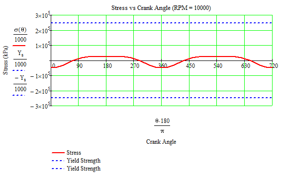
Compute the failure at RPM = 10,000.
Derive the piston displacement equation as a function of crank angle (q).
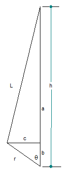
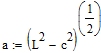
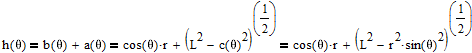
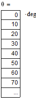
We know from Figure 2 the following relationships where we let, for example
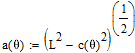
Changing the equations derived above into functions yields:
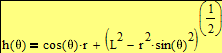
The displacement equation (as a function of the crank angle (q)) is therefore:
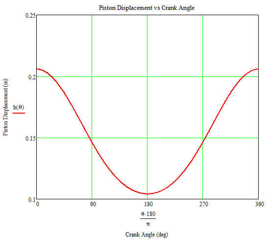
The piston displacement (the linear distance measured from center of crankshaft to piston pin) graph relative to the crank angle in the domain of 0 to 360 degrees is shown to the right.
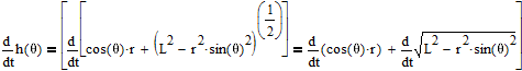
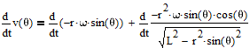
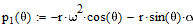
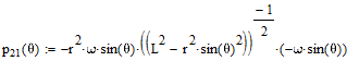
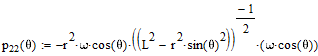
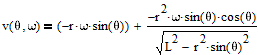
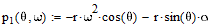
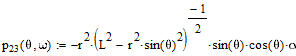
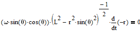
Calculating piston velocity by taking derivative of the displacement function with respect to time:
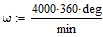
breaking into 2 parts and recalling w = angular velocity (RPM) since:
(the time rate of change of the crank angle)
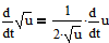
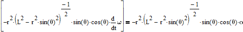
Remembering from calculus:
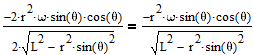
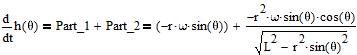
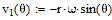
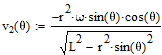
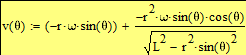
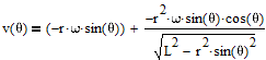
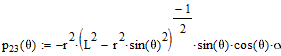
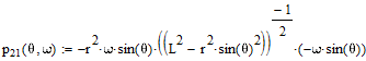
and break the velocity equation into parts
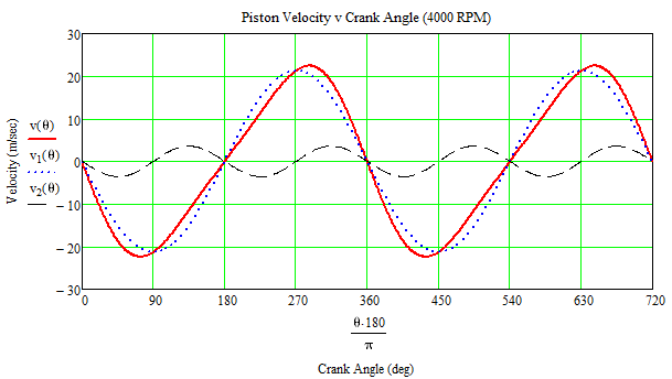
(the complete velocity equation)
Graphing this function over the domain:
Maximum velocity occurs at 73.39 degrees before and 285.61 after Top Dead Center as shown in the calculations (roots of the velocity curve) below:
using an inital guess of:
L (rod length = 6.1 in)
r (crank throw which is 1/2 of stroke) = 2 in
using an inital guess of:
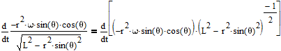
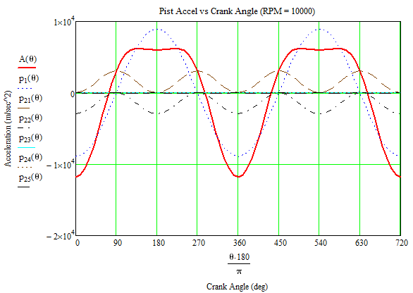
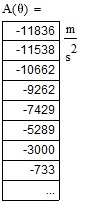
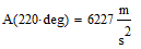
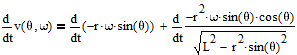
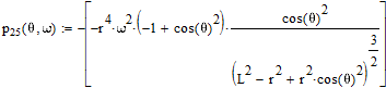
Derive the piston acceleration (a) equation:
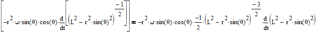
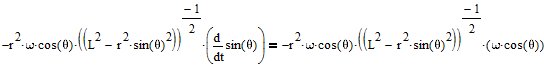
Taking the derivative of the velocity with respect to time:
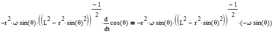
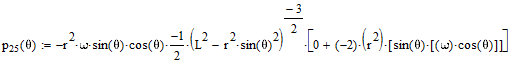
Breaking the derivation into parts:
( since crank throw does not change with time )
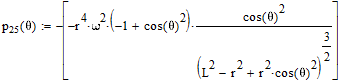
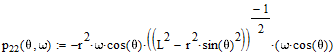
Adding the parts together to get the complete acceleration function and graphing it it over the domain:
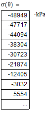
Connecting rod stress analysis:
Yield Strength of rod steel:
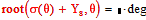
Finding failure crank angles using Mathcad's root finding function with initial guesses of:
Conclusion: For the given geometry and parameters (RPM = 10,000), the failure will occur near TDC (from 26 degrees before until 26 degrees after TDC)
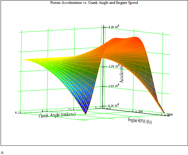
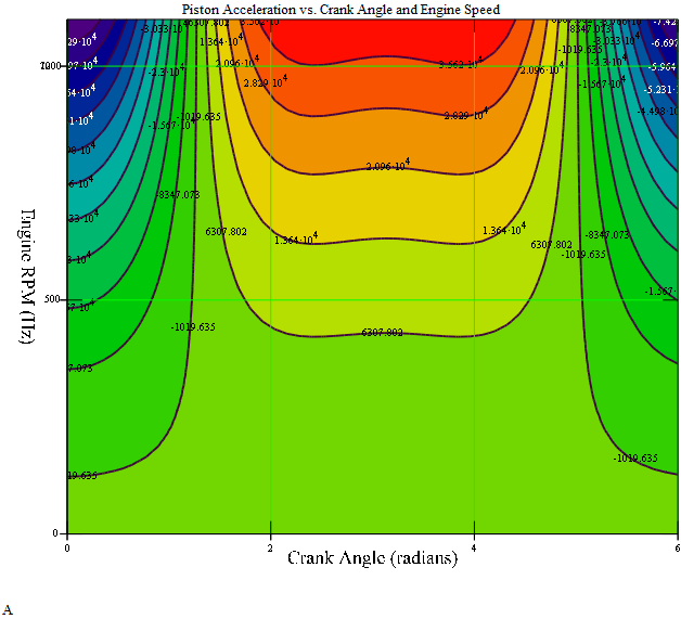
Graphing in 3D and contour plot the piston acceleration (a) equation as a function of crank angle (q) and engine RPM (w).
Taking the derivative of the velocity with respect to time:
Breaking the derivation into parts:
( since crank throw does not change with time )
Adding the parts together to get the complete acceleration function and graphing it it over the domain:
(Hz) where: 1100 Hz = 10504 RPM